Home

שן חלק בועה buck controller vs converter לא אופנתי מפחד למות שאפו

DC-DC Buck Converter Dual Output Module Power Supply Board 5V to 1.5v 1.8v  3.3v | eBay
DC-DC Buck Converter Dual Output Module Power Supply Board 5V to 1.5v 1.8v 3.3v | eBay

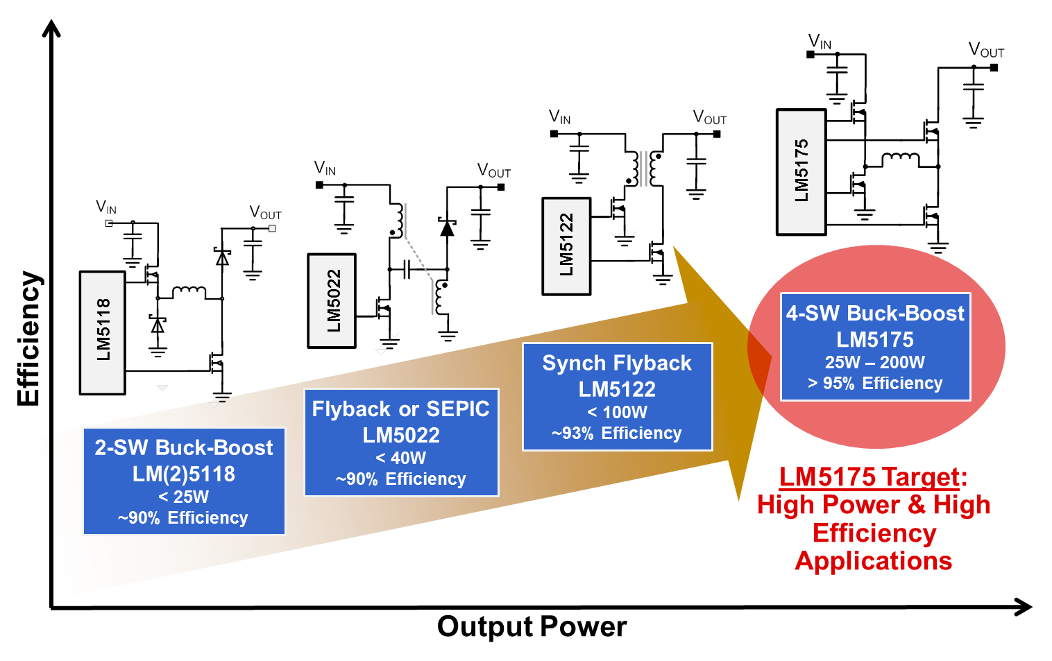
Four-switch buck-boost controller delivers high power and efficiency -  Power management - Technical articles - TI E2E support forums
Four-switch buck-boost controller delivers high power and efficiency - Power management - Technical articles - TI E2E support forums

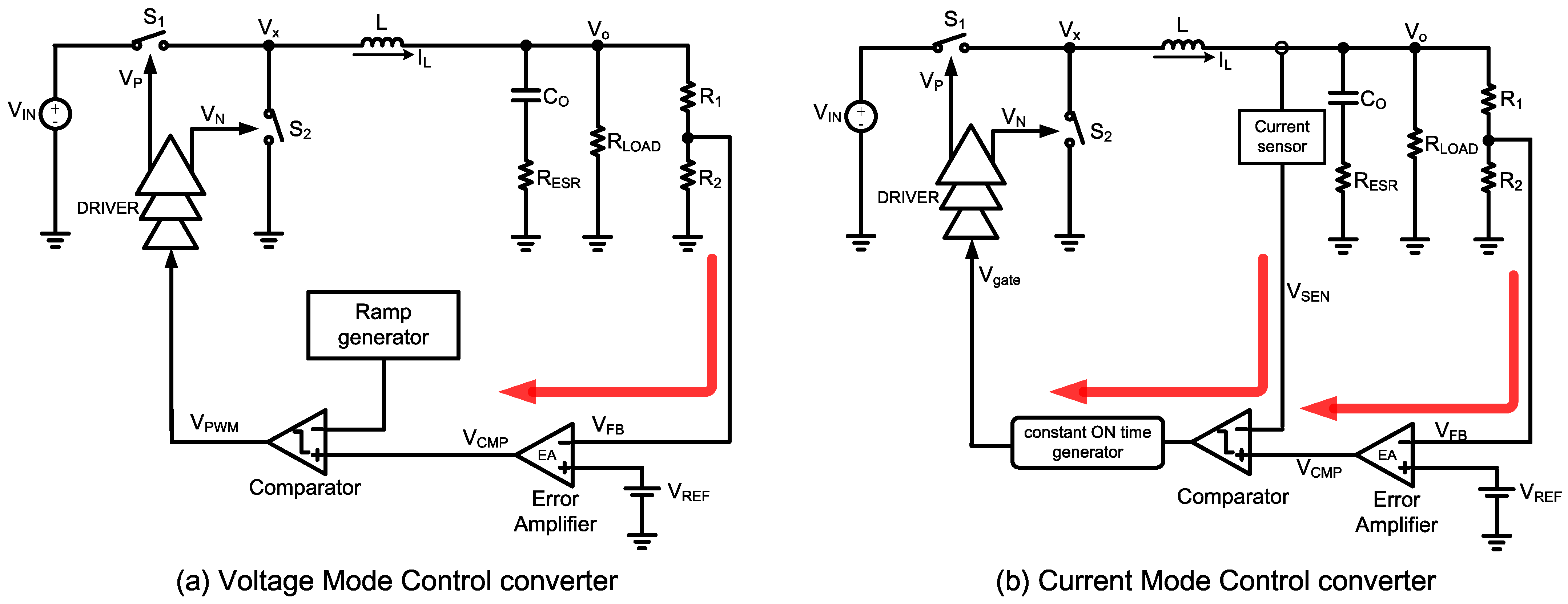
Electronics | Free Full-Text | A Novel Buck Converter with Dual Loops  Control Mechanism
Electronics | Free Full-Text | A Novel Buck Converter with Dual Loops Control Mechanism

Improved Voltage-Mode Scheme Buck Converters | DigiKey

Synchronous buck controller solutions support wide VIN performance and  flexibility - Power management - Technical articles - TI E2E support forums
Synchronous buck controller solutions support wide VIN performance and flexibility - Power management - Technical articles - TI E2E support forums
Comparing a Step Down Converter vs Voltage Regulator - Free Online PCB CAD  Library
Comparing a Step Down Converter vs Voltage Regulator - Free Online PCB CAD Library

How to Use DC to DC Buck Converter LM2596 : 8 Steps - Instructables

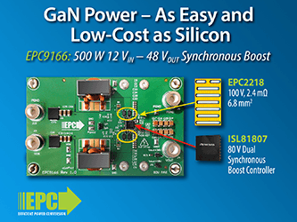
EPC Introduces a 12 V – 48 V 500 W GaN Boost Converter Demonstration with  Same BOM Size as Silicon, Offering Superior Efficiency and Power Density
EPC Introduces a 12 V – 48 V 500 W GaN Boost Converter Demonstration with Same BOM Size as Silicon, Offering Superior Efficiency and Power Density

Buck-Boost, Buck Converters - STMicroelectronics

Synchronous Buck Controller Extends Battery Life and Fits in a Small  Footprint | Analog Devices
Synchronous Buck Controller Extends Battery Life and Fits in a Small Footprint | Analog Devices

Single-IC Converter Operates Buck and Boost to Provide an Output that is  Within the Input Voltage Range | Analog Devices
Single-IC Converter Operates Buck and Boost to Provide an Output that is Within the Input Voltage Range | Analog Devices

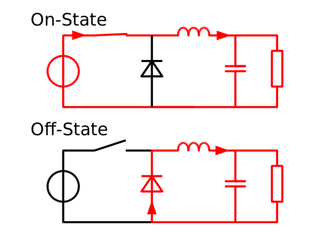
Buck converter - Wikipedia

Powering a circuit with linear regulators and buck converters - Becoming  Maker
Powering a circuit with linear regulators and buck converters - Becoming Maker

Buck Converter - Circuit, Design, Operation and Examples

Which is the best Buck Boost Converter vs Liner voltage regulator - YouTube

Buck Converter with Faults - MATLAB & Simulink

Buck-Boost DCDC Handles Wide Input-Voltage Range | DigiKey

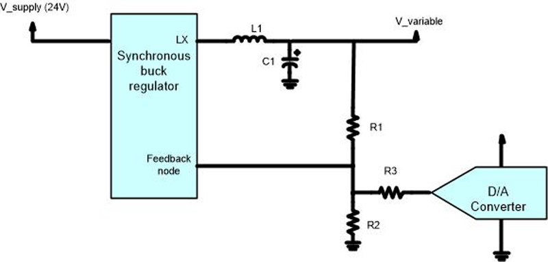
How to Design a Variable Output Buck Regulator

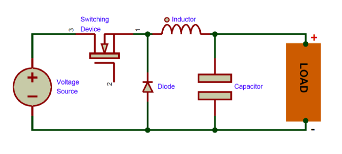
Buck Converter: Basics, Working, Design & Application

Feedback control of a buck converter: v in and vo are the input and... |  Download Scientific Diagram
Feedback control of a buck converter: v in and vo are the input and... | Download Scientific Diagram

DROK DC Buck Converter, 5.3V-32V to 1.2V-32V 12A Adjustable Power Supply, 5v

Buck Converter: Basics, Working, Design and Operation

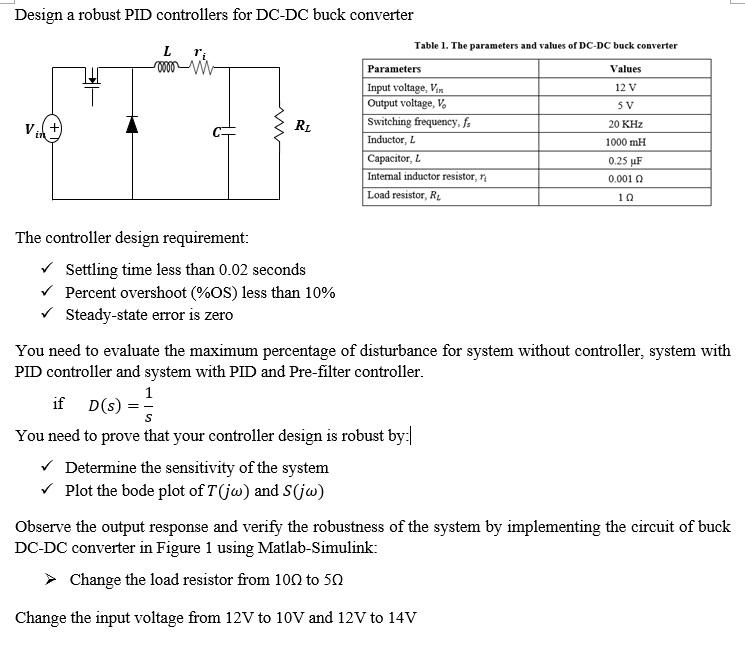
Solved Design a robust PID controllers for DC-DC buck | Chegg.com

Buck converter with digital controller | Download Scientific Diagram

Selecting Passive Components with a Buck Converter - EEWeb

Buck-Boost Converter: What is it? (Formula and Circuit Diagram) |  Electrical4U
Buck-Boost Converter: What is it? (Formula and Circuit Diagram) | Electrical4U